Table of contents
 | The ER-301 contains sensitive electronics, especially on its CPU board. These electronics are exposed just like they are on a graphics card that you would install in a PC. Therefore when handling the ER-301, you must take proper precautions to not expose it to ESD such as from static electricity. This means keeping your body properly grounded throughout any procedure where your ER-301 is not connected to your case. |
Replacing the CPU Board
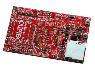
This is the CPU board on the back of the ER-301. It holds the CPU, RAM and the SD card which contains the firmware. This CPU board is manufactured by another company called Olimex.
This process is easy and safe as long as you take your time, take basic anti-static precautions and do not force anything.
- Purchase a replacement CPU board (AM3352-SOM) from Olimex for about 37EUR.
- Remove the rear SD from the old CPU board and insert it in the SD slot on the new CPU board.
- Carefully remove the old CPU board by prying up each side little-by-little. Do NOT try to forcefully pull it off all at once. Here is a step-by-step tutorial on how to remove the CPU board.
- Carefully align the pins and push on the new CPU board. It is very important that you use both hands, pressing ONLY on all 4 corners evenly. Do not push on the center of the board and especially do not push on the area with the Olimex logo. Underneath the logo is the RAM chip which might be damaged if you press here.
Removing the panel
You will need…
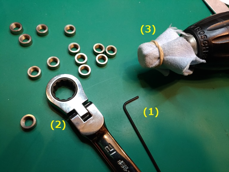
- a 1.5mm allen wrench for the knob’s set screw.
- a 12mm socket wrench for the nut on the encoder bushing. An adjustable wrench is fine for this also.
- an 8mm socket wrench for the jacks. Cover the end of the socket wrench with felt or any similar cloth. The finger-tip of an old glove also works.
Some things to watch out for according to users:
- Be careful with the amber acrylic display lenses. They can be scratched easily by rubbing against components that are attached to the circuit board. (thread)
- Work in a very dust free area, as the displays and lenses tend to attract dust, and it can get caught between the OLEDs and the acrylic when reassembling. Having a tape loop of blue painter’s tape can help grab any dust off the acrylic or displays without putting any tiny scratches in the acrylic lenses. (thread)
Replacing buttons
It is not hard to replace the button caps and internals (spring and upper contact plate). Some reasons for replacing buttons are:
- Customizing the colors.
- Cleaning or replacing corroded contacts.
- Fixing a sticky button.
I find that prying off the button caps is most conveniently done with a 2mm flathead screwdriver. Here is what the process looks like:
| | Inside the button cap is a spring and contact plate. If you are going to re-use them then be careful not to lose the spring (like I did in the video) and take care not to bend the contact plate. |
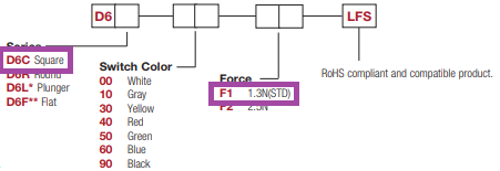
How to purchase new buttons
The part number for the gray buttons is D6C10-F1-LFS. There are other colors available but make sure you order the square type with 1.3N of actuating force:
Replacing toggle switches
Replacing a toggle switch requires the ability to desolder and solder through-hole components. All of my modules come with long flat toggles (part number: ATE1E-2F3-10-Z) but there is an alternative part with a short round paddle (part number: ATE1E-2M3-10-Z) that can be used as a drop-in replacement.
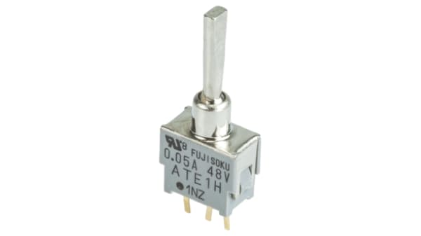
ATE1E-2F3-10-Z: This is the default toggle with a long flat paddle.
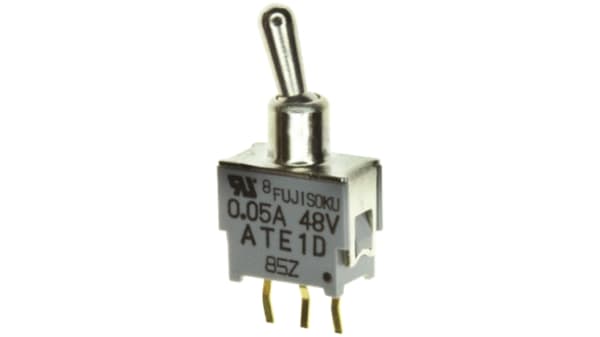
ATE1E-2M3-10-Z: This is an alternative toggle with a shorter round paddle.