Sample Scanner Unit
Use a sample as an interpolated lookup table.Overview
This unit lets you (flexibly) turn any sample into an interpolating lookup table. If you understand the Bump Scanner, then the Sample Scanner is exactly the same with the (entire) sample taking the place of the bump. The incoming CV selects a position in the sample (i.e. indexes into the lookup table) and the unit outputs the value (or an interpolated value if the position falls between two samples). Most of the complexity of this unit comes the controls that allow you to locate the entire sample somewhere on the input CV range.
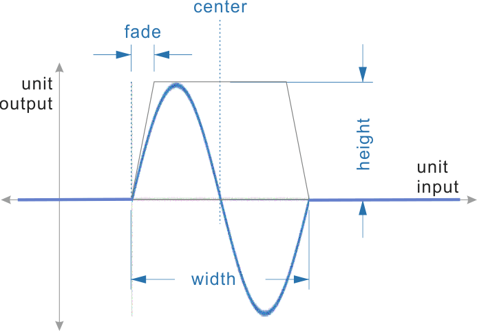
In the figure above, a sample containing a single cycle of a sine wave has been loaded into the unit. This diagram above is not showing the output signal vs time. The x-axis is not time, but rather the input signal. The diagram shows how the output signal is derived from the input signal. The graph should be read like a lookup table. The center parameter locates the sample in the unit’s input range. The width parameter determines how much of the unit’s input range is covered by the sample. The height parameter adjusts the amplitude of the sample values, while the fade parameter dictates the percentage of the width used to fade out the sample’s edges to zero.
Some applications are:
- Quantizate to custom-made scales or grids
- Wave-shaping
- Use CV (such as an LFO) to ‘'’scan a sample’’’ as an interpolated look-up table (i.e. the name-sake application).
 | Don’t be fooled! This unit is not a wavetable synthesizer, for that see the Single Cycle Unit. There is no frequency-controlled phase accumulator here. Instead the input signal is used to directly lookup output values from a lookup table. The lookup table just happens to be loaded from a sample. |
| | This unit applies an internal gain of 2.0 to the input signal. For input signals with a range greater than +/-0.5 (or +/- 5V for external signals), you will want to attenuate them with a Linear Bipolar VCA or some other amplification Unit prior to connecting to the Sample Scanner. |
Parameters
center
The center parameter controls where the center of the sample should be placed on the input range.
width
The width parameter controls how much of the input range the sample covers.
height
The height parameter adjusts the amplitude of the sample values.
fade
The fade parameter dictates the percentage of the width used to fade out the sample’s edges to zero.
phase
The phase parameter rotates the sample within its boundaries with wrap-around.