What is I2C?
I2C is a hardware bus specification that allows 2 or more integrated circuits to communicate over two wires plus ground. I2C was designed for closed systems where the electrical characteristics of all bus connections and participants are known beforehand. As an end user, this means you should acknowledge that I2C is not a hardened consumer-oriented technology and all use of I2C to connect the ER-301 to other devices is at your own risk. Using I2C exposes sensitive circuitry of the ER-301 to ESD risks so precautions must be taken when designing your I2C-connected system. It is best to think of it as a form of community-supported factory-enabled hacking.
Where is the I2C header?
The first few runs of the ER-301 did not have a dedicated i2c header. Instead users would perform a small hardware modification (described here) so that they could use the exposed UART header instead.
Connecting the Teletype to the ER-301
In a nutshell, i2c requires 2 communication lines (SCL and SDA) plus 1 ground line. So there are 3 pins on the Teletype that need to be connected with a custom cable to 3 pins on the ER-301.
 | Since these connection pins were originally meant for UART communication you will need to perform a simple hardware modification to your ER-301 in order to enable i2c communication. Please refer to the I2C Mod section below for further instructions. |
Please note: The ER-301 does not ship with i2c cables. Here is some info on how to DIY your own cables: DIY i2c cables @ LINES forum.
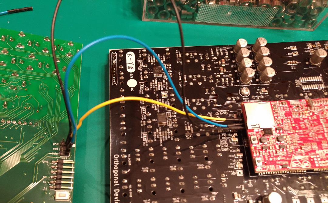
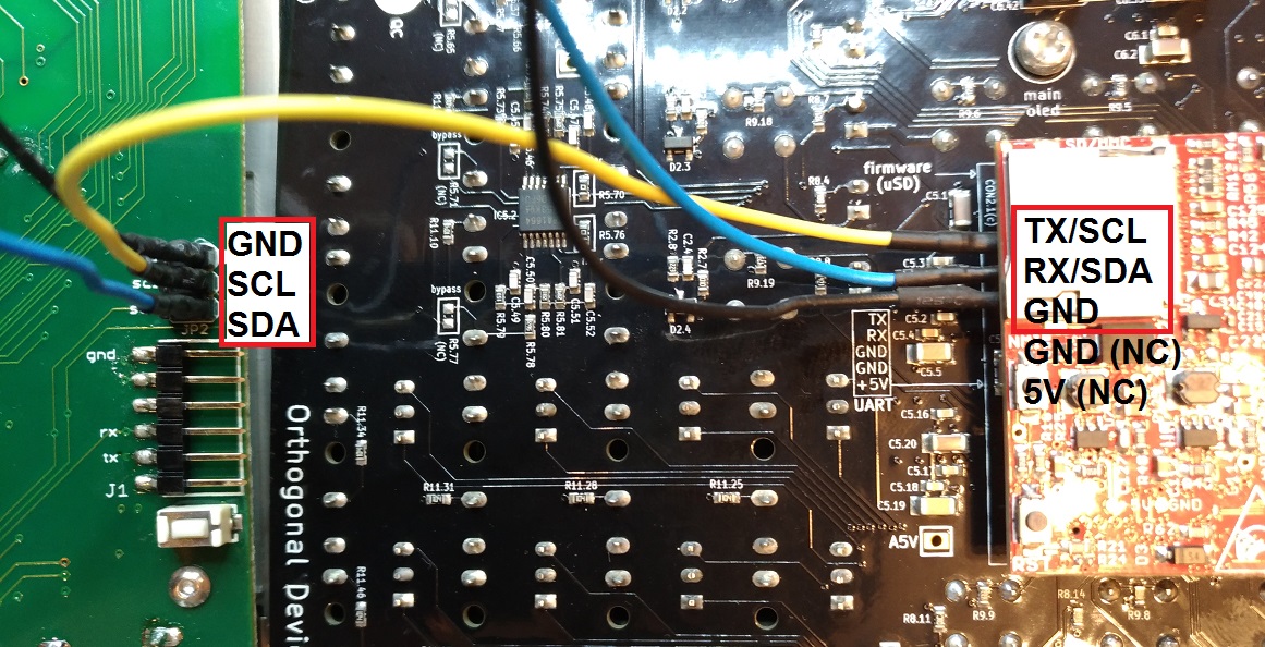
There are 5 pins extending parallel from underneath the ER-301 CPU board. You will only be using the top 3. You can also see that the 5 pins are labeled on the ER-301 silkscreen as TX, RX, GND, GND, and 5V. Connect like this:
- Teletype GND to ER-301 GND.
- Teletype SCL to ER-301 TX.
- Teletype SDA to ER-301 RX.
 | Since the ER-301 does not ship with i2c cables, you will need to make your own. Here is some info on how to DIY your own cables: DIY i2c cables @ LINES forum |
Required Hardware Modification
| | If your ER-301 board revision is revision 10 or later then this modification is NOT necessary. |
The goal of this hardware modification is to short out the diode labeled D3 on the red CPU board on the back of the ER-301. The diode’s original purpose was to provide level-shifting for the RX pin of the UART port. Shorting out this diode allows for this pin to be used for the SCL (clock) pin of i2c.
| | It is not necessary to remove the CPU board in order to perform this modification. |
Required tools:
- Soldering iron (ESD-safe, reliable temperature control) and solder (recommend no-clean flux)
- Short length of solid core wire (or waste lead from a through-hole resistor or LED or similar)
- needle-nose pliers (optional)
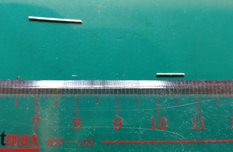
Step 1: Cut a 7mm piece of solid core wire or use part of a lead from a resistor or LED.
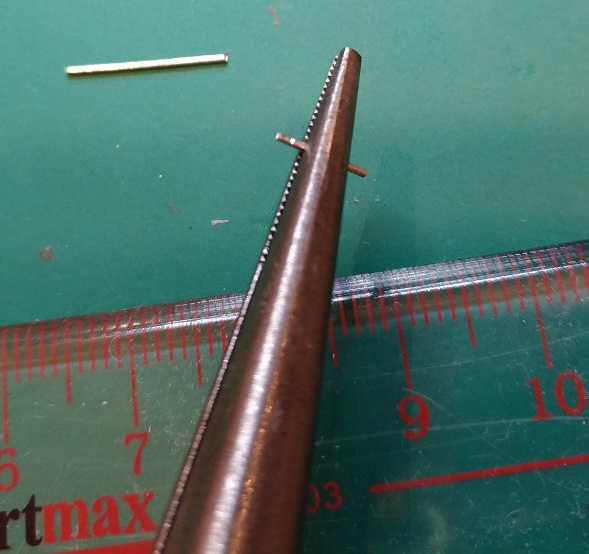
Step 2: Bend it around some needle-nose pliers.
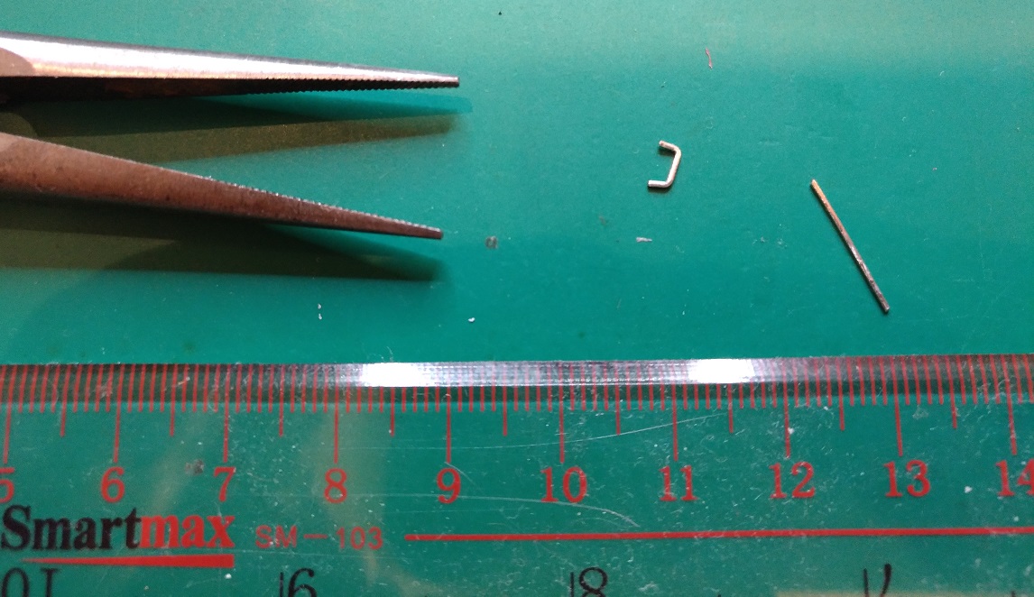
Step 3: You should have a nice boxy U-shape like this.
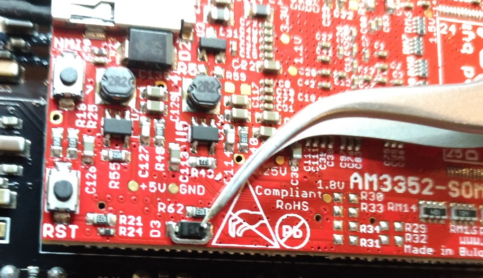
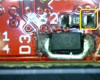
Step 4: Place around diode D3 like this with the bottom of the U oriented towards the bottom of the board so that we do not short resistor R62.
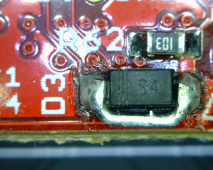
Step 5: And solder like this.
Step 6: Check continuity between the right side of R62 and the RX/SDA pin of the UART connector.
| | Do not use a solder sucker on this board. If you need to remove excess solder, please use copper braid. |